Phase 4 — Wire I2C + scan
Add SDA / SCL and confirm SHT40 and BMP390 answer on the bus. Power from Phases 2–3 stays on.
Firmware
Changed. New folder firmware/04-i2c-scan/. Do not edit 01-hello. Pins SDA=8 SCL=18.
Preconditions
- Checkpoint 3 passed
- Sensor VCC/GND already on the 3V3 star
- Unplug USB while seating the two data jumpers
4.1 Data wires
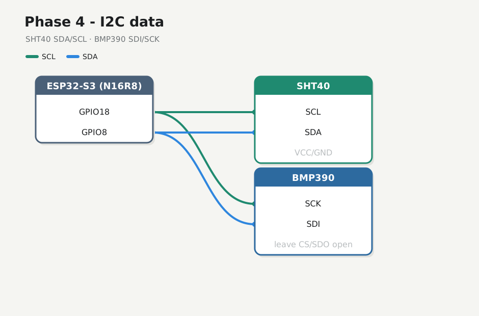
| S3 | SHT40 | BMP390 (I2C silk) |
|---|---|---|
| GPIO8 | SDA | SDI (sometimes labeled SDA) |
| GPIO18 | SCL | SCK |
BMP390 breakouts usually don’t print SCL/SDA — they reuse SPI names. For I2C: SCK = clock, SDI = data. Leave BMP390 CS and SDO open (Adafruit pinouts).
Both wires or nothing — one alone → found none. Do not wire TFT SPI yet.
4.2 Flash scanner
Stop any serial monitor on COM first.
cd firmware/04-i2c-scan
pio run -e esp32-s3-n16r8 -t upload --upload-port /dev/ttyACM0
Connected to ESP32-S3 on /dev/ttyACM0:
…
Hash of data verified.
Hard resetting via RTS pin...
========================= [SUCCESS] Took 13.70 seconds =========================
pio device monitor -b 115200 --port /dev/ttyACM0
weather i2c-scan — phase 4
SDA=GPIO8 SCL=GPIO18 expect=SHT40~0x44 BMP390~0x76/0x77
--- i2c scan ---
found 0x44
found 0x77
devices=2
Expect 0x44 (SHT40) and 0x76 or 0x77 (BMP390) every scan. This bench: 0x44 + 0x77, stable. Note any other addresses as ghosts.
4.3 If no device
- Confirm both data wires seated on each module (BMP390: SDI+SCK, not CS/SDO)
- Recheck data/clock not swapped
- Shared GND confirmed on the star
- Shorter jumpers; power still ~3.3 V on each VCC
Checkpoint 4
- [x] Serial scan lists SHT40 (~
0x44) and BMP390 (~0x76/0x77) - [x] Addresses stable across resets
- [x] Logged in lab-log.md
Stop here until checkpoint passes.
Next: Phase 5 — Climate read