Phase 3 — Power the sensors
Four wires: SHT40 and BMP390 supply only. TFT power from Phase 2 stays. No I2C data yet.
Firmware
Unchanged — firmware/01-hello/.
Preconditions
Checkpoint 2 passed. One SHT40 and one BMP390 on the breadboard. Unplug USB while seating jumpers.
Warning
Power the modules from 3V3 only — 5V on the logic can kill them. After wiring, check for heat and ~3.3 V on each VCC before trusting it.
Wires
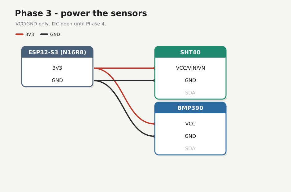
| From S3 | To |
|---|---|
| 3V3 | SHT40 VCC / VIN / VN, BMP390 VCC / VIN |
| GND | SHT40 GND, BMP390 GND |
Tap the breadboard 3V3 / GND star (how the board is tied) — don’t daisy-chain module-to-module for power. Silk may say VCC, VIN, VN, or 3Vo — same 3V3 rail as TFT VDD. Leave SDA / SCL open until Phase 4.
Check
Plug COM. Modules cool. Meter ≈ 3.3 V on each sensor VCC. TFT backlight still on. Hello still prints.
pio device monitor -b 115200 --port /dev/ttyACM0
weather hello MAC=28:84:85:8C:D0:40 uptime_ms=1624
Checkpoint 3
- [x] Those four sensor power wires only (TFT power still on)
- [x] ~3.3 V on each VCC, no heat
- [x] Hello still prints
- [x] Lab log
Next: Phase 4 — I2C scan